Protective Relays
Protective relays are critical components in electrical power systems, designed to detect and respond to abnormal conditions such as faults and overloads. These devices are essential for ensuring the safety and reliability of electrical networks by isolating faulty sections, thereby preventing damage to equipment and maintaining system stability.
| Protective Relays | |
|---|---|
Types of Protective RelaysProtective relays can be categorized based on their function, operating principles, and applications. Here are some of the most common types:
Overcurrent Relays:
Differential Relays:
Distance Relays:
Directional Relays:
Ground Fault Relays:
Motor Protection Relays: Protective Relay ApplicationsProtective relays are used across various segments of the electrical power system, including:
Generation:
Transmission:
Distribution:
Industrial Systems:
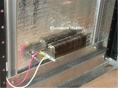
Commercial and Residential Buildings: Medium Voltage Switchgear
Voltage Level:
Components:
Applications:
Example: 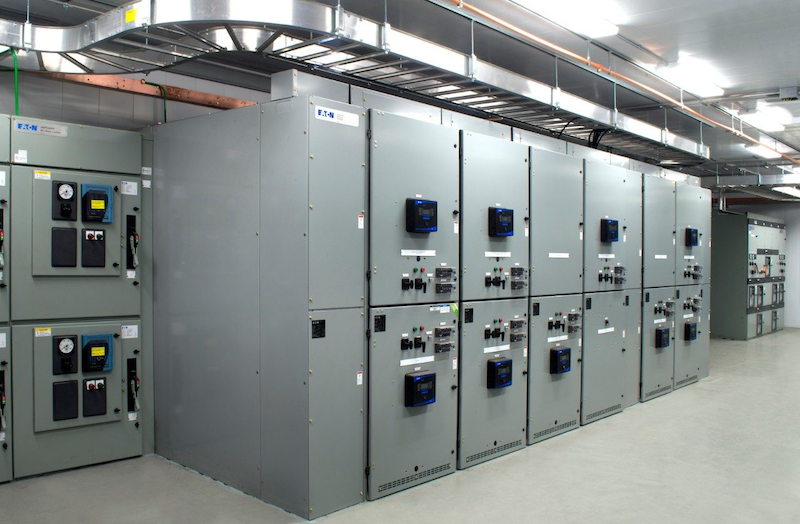
Switchgear Test ProceduresVisual and Mechanical Inspection:
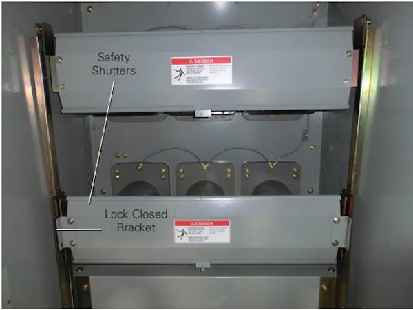
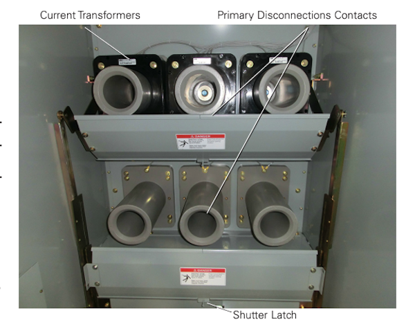
Perform visual and mechanical inspection of Instrument Transformers (CTs, VTs)Perform visual and mechanical Control Power Transformers (CPT)
Electrical Tests :
|
|
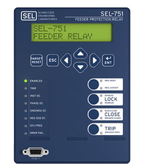
| SEL Relays | ||||||||||||
|---|---|---|---|---|---|---|---|---|---|---|---|---|
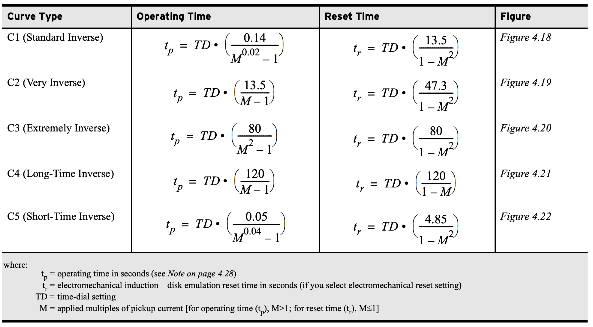
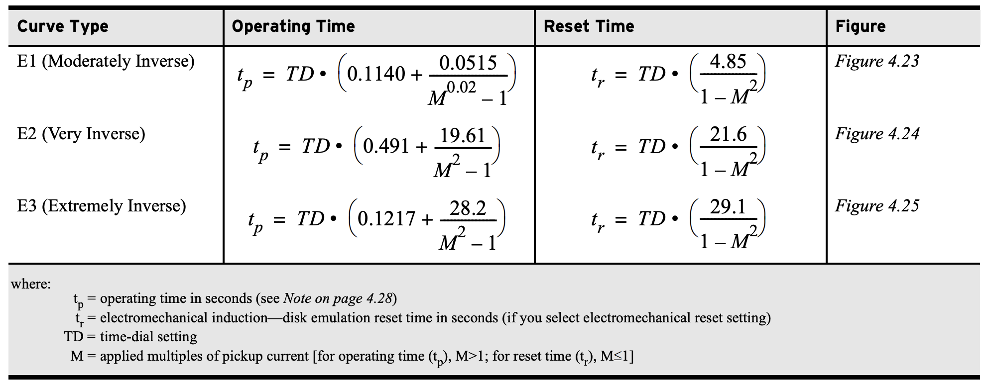
Time Overcurrent Operating Times (51)Percent Error Calculator\( \Large\frac{(X_{Meas}-X_{Calc})}{X_{Calc}} \times 100 \) SEL Time Overcurrent Equations (51 Function)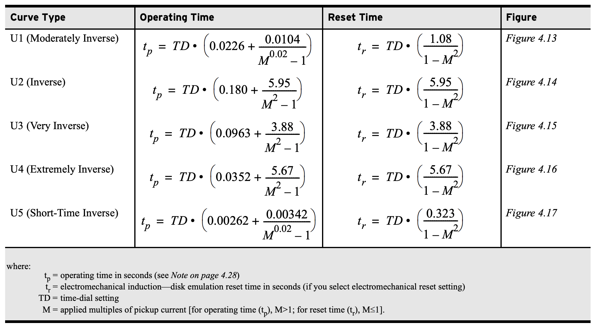
Metering CalculatorInput ValuesPhase Power
Phase Rotation
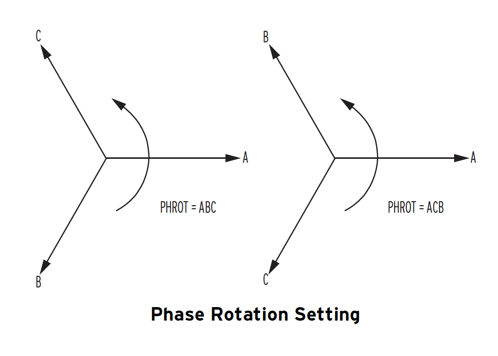
Input ValuesABC Rotation
Va = VMAG∠0
Ia = IMAG∠0 ACB Rotation
Va = 67∠0
Ia = 2.5∠0
SEL Metering Instructions
Delta Configured PTABC Rotation
Va (VAB) = 67∠30
Ia = 2.5∠0 ACB Rotation
Va = 67∠0
Ia = 2.5∠0
Example Settings:
Total Watts
3P = 3 * 2.5 * 67 * 0.899 * CTR * (PTR/1000)
Total Vars
3Q = 3 * 2.5 * 67 * 0.438 * CTR * (PTR/1000) WYE Configured PTABC Rotation
Va = 67∠0
Ia = 2.5∠0 ACB Rotation
Va = 67∠0
Ia = 2.5∠0
Example Settings:
Total Watts
3P = 3 * 2.5 * 67 * 0.899 * CTR * (PTR/1000)
Total Vars
3Q = 3 * 2.5 * 67 * 0.438 * CTR * (PTR/1000) Terminal Commands=>> SET -n- -m- -s- TERSE where: G, R, or P = (parameter “n” is not entered for the Group settings). m = group (1 or 2) or port (1, 2, 3, or F). The relay selects the active group or port if “-m-” is not specified. s = the name of the specific setting you wish to jump to and begin setting. If “-s-” is not entered, the relay starts at the first setting. TERSE = instructs the relay to skip the SHOWSET display after the last setting. Use this parameter to speed up the SET command. If you wish to review the settings before saving, do not use the TERSE option. Password
ACC Access to level 1 commands: Metering Data
MET Display meter data Adjust Setting Values
SET n Enter group settings Pulse Output Contacts
PUL n k Pulse Output n for k seconds Show Data
TAR Show target values Event Recorder Data
EVE Show event record Clock
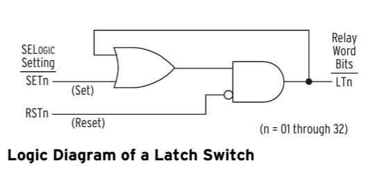
DAT Show or set date Latch BitsLatch control switches (latch bits are the outputs of these switches) replace traditional latching devices. Traditional latching devices maintain output contact state. The SEL-700G latch control switch also retains state even when power to the device is lost. If the latch control switch is set to a programmable output contact and power to the device is lost, the state of the latch control switch is stored in nonvolatile memory, but the device de-energizes the output contact. When power to the device is restored, the programmable output contact goes back to the state of the latch control switch after device initialization. Traditional latching device output contact states are changed by pulsing the latching device inputs (see Figure 4.141). Pulse the set input to close (set) the latching device output contact. Pulse the reset input to open (reset) the latching device output contact. The external contacts wired to the latching device inputs are often from remote control equipment (for example, SCADA, RTU). 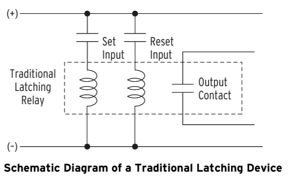
SV Logic Variables(Variables/Timers)
Timers Reset When ower Lost or Settings Changed 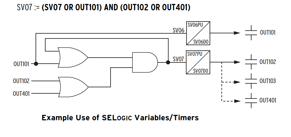
SV/Timers Settings \( I_{NOM} = [\Large \frac{\frac{ \Large MVA \times 1000}{ \Large 1.73 \times kV}}{CTR} ] \)
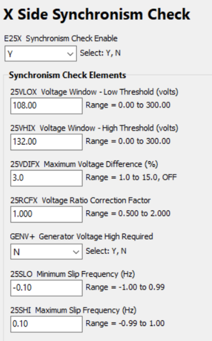
where: The relay directional power, negative-sequence overcurrent, and differential elements use the INOM setting. Input Values
Vnom
Inom
MTA
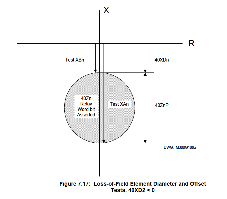
40Z1P
40XD1
40Z1D
40Z2P
40XD2
40Z2D
Output Values
0.45 is an arbittrary pick up point
|
||||||||||||


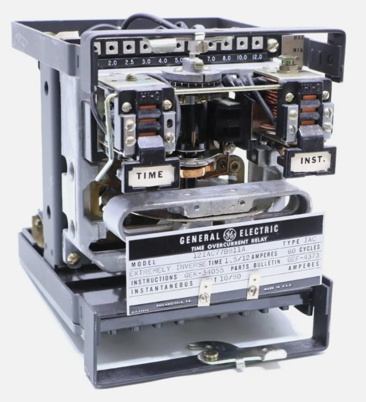
| GE Relays | |
|---|---|
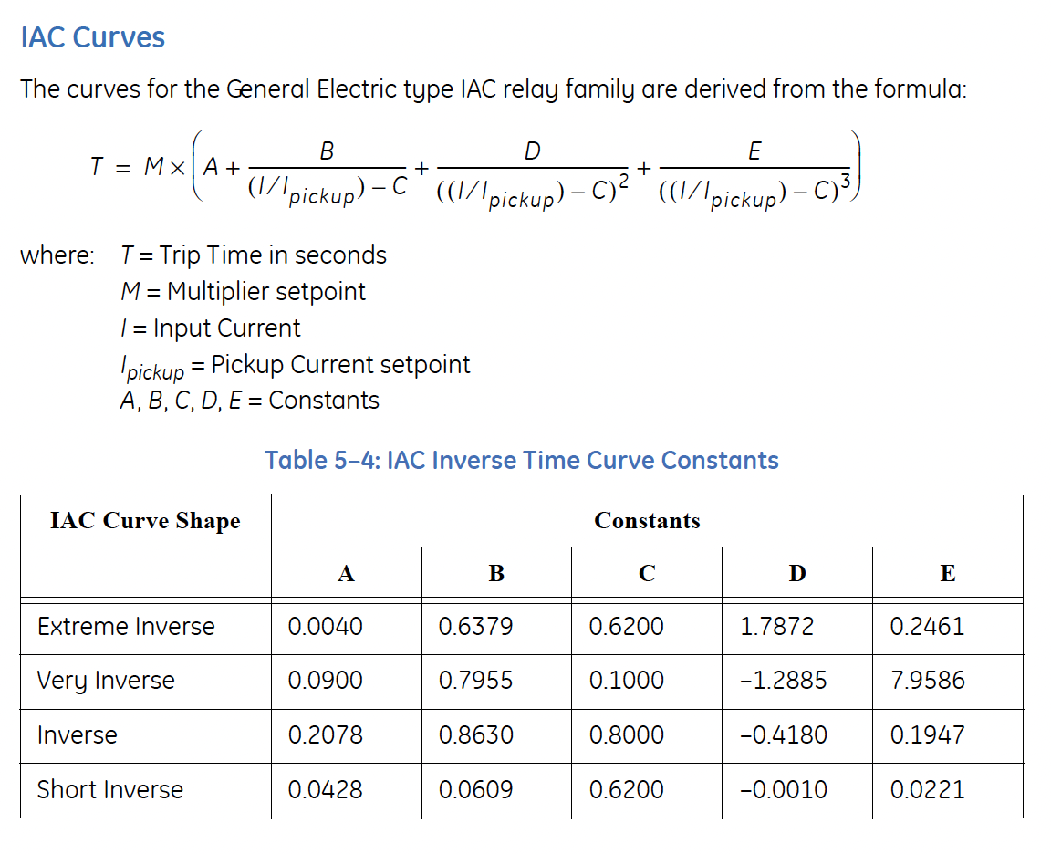
Time Overcurrent Operating Times (51)Percent Error Calculator\( \Large\frac{(X_{Meas}-X_{Calc})}{X_{Calc}} \times 100 \) GE Time Overcurrent Equations (51 Function)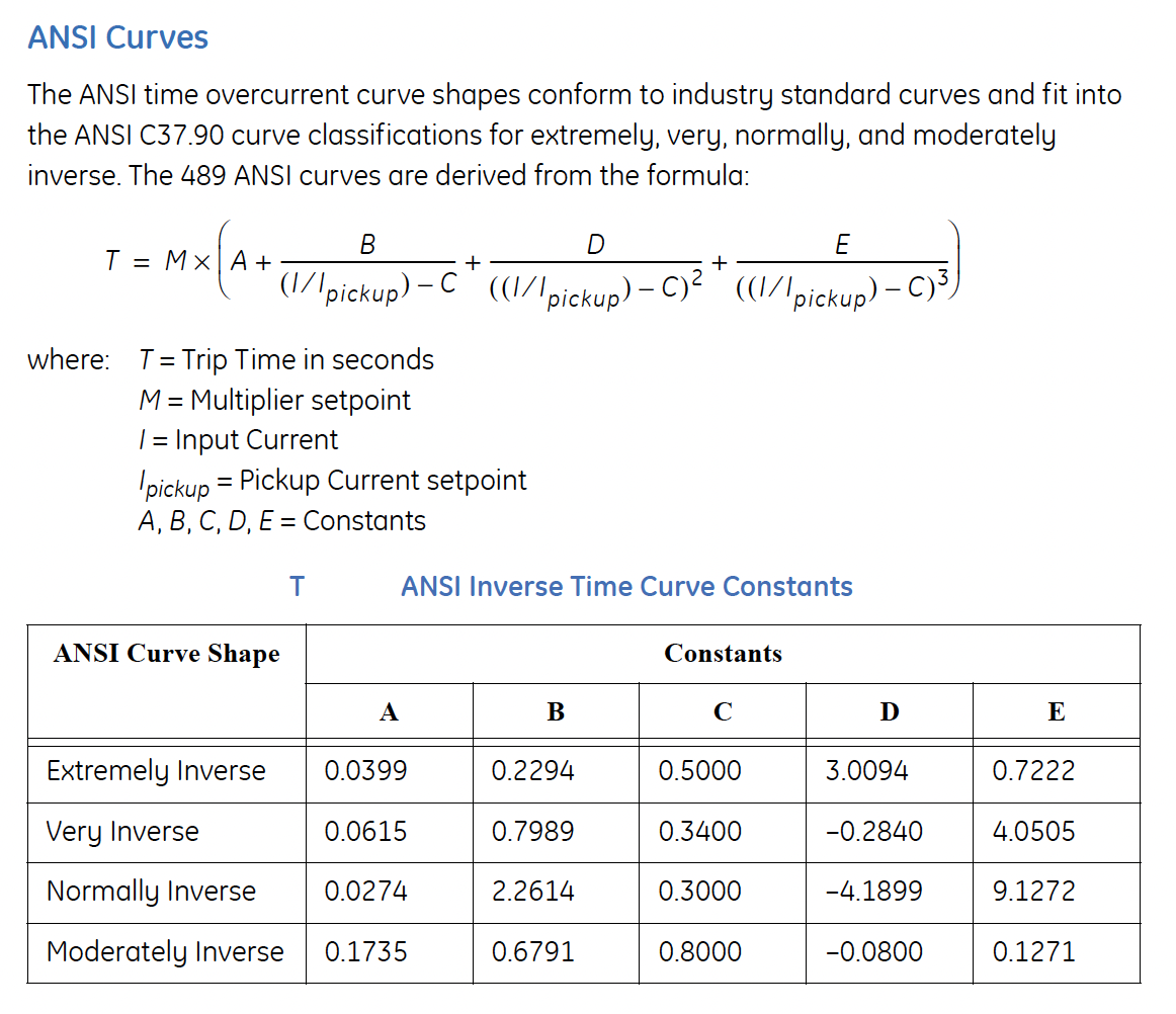
Setting is a % of Rated MW
GEN. PARAMETERS
Generator Rated MVA 2.500 MVA
Given: Phase CT Primary 400 A
VOLTAGE SENSING
VT Connection Type
MW = MVA Rating * power factor Rating
MW = 2500MVA * 0.8= 2000MW Trip Current = 0.52A
Current Sensing
Voltage Sensing
Gen. Parameters:
Negative Sequence Settings:
Setting is a % of FLA \( Gen \; FLA =\frac{ MVA}{ \sqrt{3} \times V_{pp} }\) \( I_{Neg \; Seq} = \frac{1}{3} (I_{a} + a^2I_{b} + aI_{c}) \) \( I_{pickup} = 3 * I_{FLA\; (sec)} * \frac{Neg.Seq-Set}{100} \)
NORM_VOLTS = Generator_Voltage_Phase_Phase / Transformer_Ratio / SQR(3) Negative-Sequence Inverse Time Curves\( K = (I_{2})^{2} \times T \)
K = constant from generator manufacturer depending on size and design; 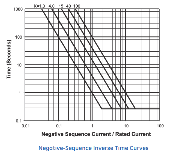
Current Sensing
Voltage Sensing
Gen. Parameters:
Negative Sequence Settings:
Setting is a % of FLA 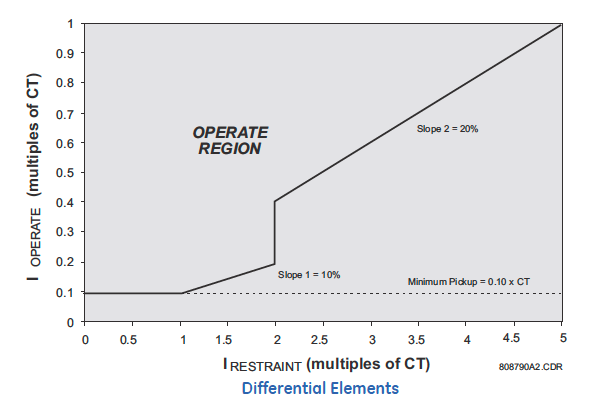
Relay Instruction ManualsRelay Application and Testing Documents |
|
| NETA Test Procedure | |
|---|---|
NETA ATS-20177.9.1 Protective Relays, Electromechanical and Solid-StateA. Visual and Mechanical Inspection:
B. Electrical Tests:
C. Test Values – Visual and MechanicalRelay Case
Relay
Relay settings shall match the coordination study or setting sheet supplied by owner.D. Test Values – Electrical
NETA ATS-20177.9.2 Protective Relays, Microprocessor-BasedA. Visual and Mechanical Inspection:
B. Electrical Tests:
C. Test Values – Visual and Mechanical
D. Test Values – Electrical
NETA ATS-20197.9.2 Protective Relays, Microprocessor-BasedA. Visual and Mechanical Inspection:B. Electrical Tests:C. Test Values – Visual and MechanicalD. Test Values – ElectricalNETA ATS-20197.9.2 Protective Relays, Microprocessor-BasedA. Visual and Mechanical Inspection:B. Electrical Tests:C. Test Values – Visual and MechanicalD. Test Values – Electrical
|
|