NETA ATS-2017
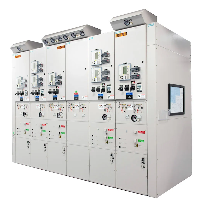
Switchgear and Switchboard
Assemblies
A. Visual and Mechanical
Inspection:
- Compare equipment
nameplate data with drawings and
specifications.
- Inspect physical and
mechanical condition.
- Inspect anchorage,
alignment, grounding, and required
area clearances.
- Verify the unit is
clean and all shipping bracing,
loose parts, and documentation
shipped
inside cubicles have been removed.
- Verify that fuse and
circuit breaker sizes and types
correspond to drawings and
coordination
study as well as to the circuit
breaker’s address for
microprocessor-communication
packages.
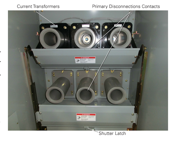
- Verify that current and
voltage transformer ratios
correspond to drawings.
- Verify that wiring
connections are tight and that
wiring is secure to prevent damage
during
routine operation of moving parts.
- Inspect bolted
electrical connections for high
resistance using one or more of the
following
methods:
- Use of a
low-resistance ohmmeter.
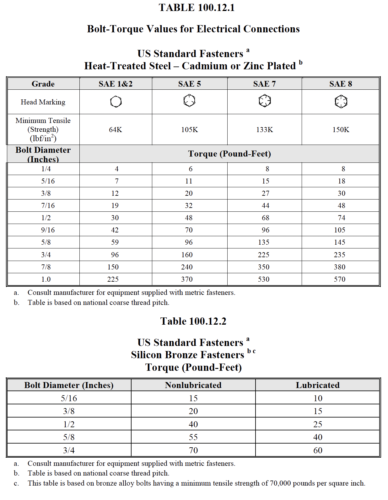
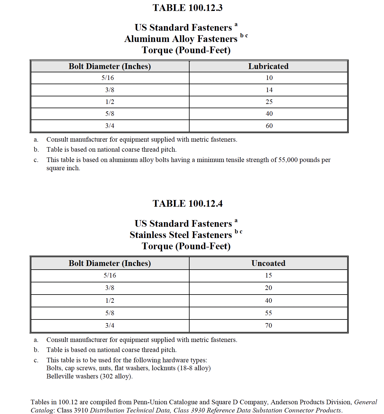
- Verify tightness of
accessible bolted electrical
connections by calibrated
torque-wrench
method in accordance with
manufacturer’s published data or
Table 100.12.
- Perform Perform
thermographic survey.
(optional).
- Verify operation and
sequencing of interlocking systems.
- Verify appropriate
lubrication on moving
current-carrying parts and on moving
and sliding
surfaces.
- Inspect insulators for
evidence of physical damage or
contaminated surfaces.
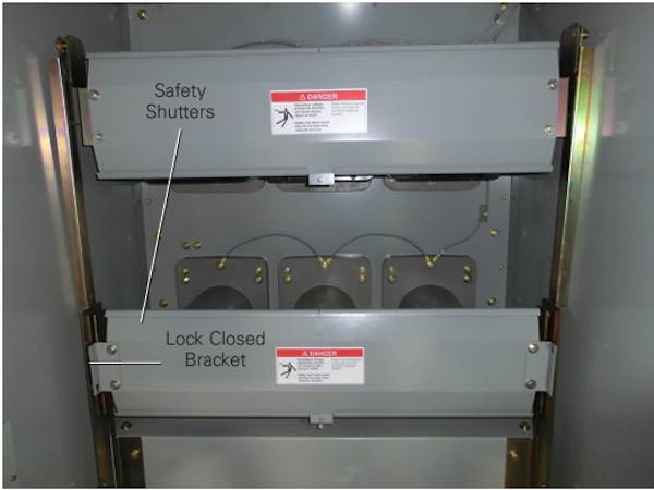
- Verify correct barrier
and shutter installation and
operation.
- Exercise all active
components.
- Inspect mechanical
indicating devices for correct
operation.
- Verify that filters are
in place and vents are clear.
- Perform visual and
mechanical inspection of instrument
transformers
- Perform visual and
mechanical inspection of surge
arresters
- Inspect control power
transformers.
- Inspect for
physical damage, cracked
insulation, broken leads,
tightness of
connections, defective wiring,
and overall general condition.
- Verify that primary
and secondary fuse or circuit
breaker ratings match drawings.
- Verify correct
functioning of drawout
disconnecting contacts,
grounding contacts, and
interlocks.
B. Electrical Tests:
-
Perform resistance measurements
through bolted connections with a
low-resistance ohmmeter,
-
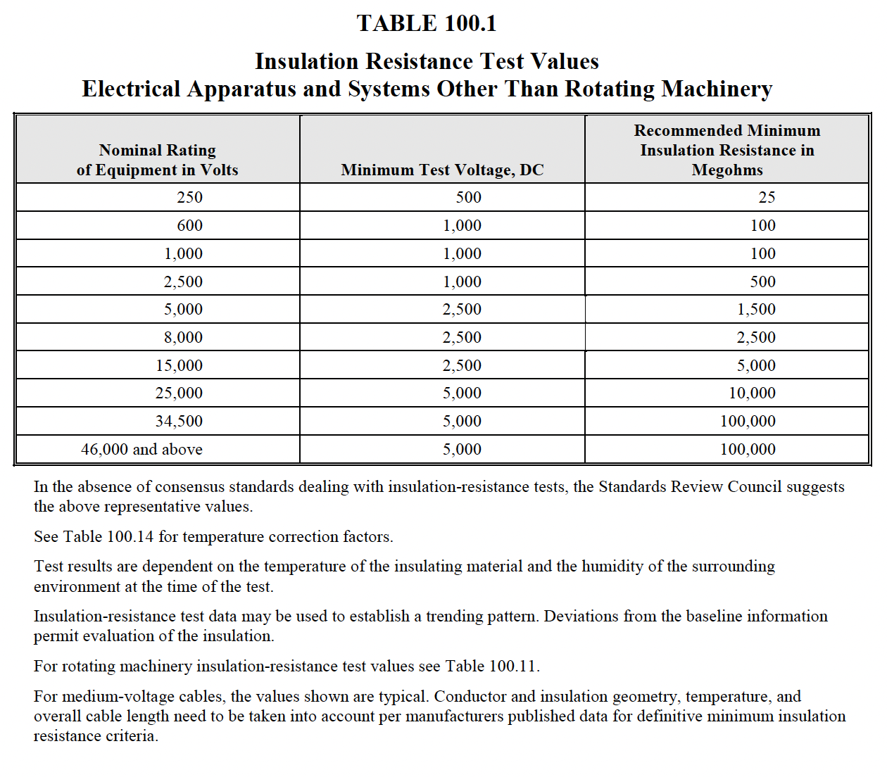
Perform insulation-resistance tests
on each bus section, phase-to-phase
and phase-to-ground,
for one minute in accordance with
Table 100.1.
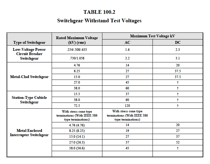
-
Perform a dielectric withstand
voltage test on each bus section,
each phase-to-ground with
phases not under test grounded, in
accordance with manufacturer’s
published data. If
manufacturer has no recommendation
for this test, it shall be in
accordance with Table 100.2.
The test voltage shall be applied
for one minute.
-
Perform insulation-resistance tests
on control wiring with respect to
ground. Applied
potential shall be 500 volts dc for
300-volt rated cable and 1000 volts
dc for 600-volt rated
cable. Test duration shall be one
minute. For units with solid-state
components or control
devices that can not tolerate the
applied voltage, follow the
manufacturer’s recommendation.
(optional)
-
Perform electrical tests on
instrument transformers
-
Perform ground-resistance tests
-
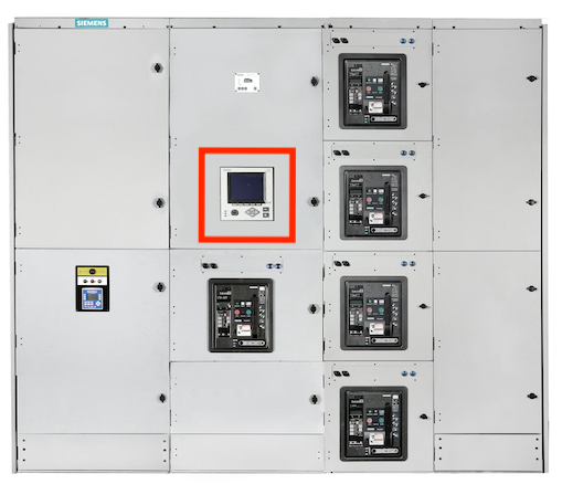
Test metering devices
-
Control Power Transformers
-
Perform insulation-resistance
tests. Perform measurements from
winding-to-winding
and each winding-to-ground. Test
voltages shall be in accordance
with Table 100.1
unless otherwise specified by
the manufacturer.
-
Perform a turns-ratio test on
all tap positions
-
Perform secondary wiring
integrity test. Disconnect
transformer at secondary
terminals and connect secondary
wiring to a rated secondary
voltage source. Verify
correct potential at all
devices.
-
Verify correct secondary voltage
by energizing the primary
winding with system
voltage. Measure secondary
voltage with the secondary
wiring disconnected.
-
Verify correct function of
control transfer relays located
in the switchgear with
multiple control power sources.
-
Voltage Transformers
-
Perform secondary wiring
integrity test. Verify correct
potential at all devices.
-
Verify secondary voltages by
energizing the primary winding
with system voltage.
-
Perform current-injection tests on
the entire current circuit in each
section of switchgear.
-
Perform current tests by
secondary injection with
magnitudes such that a minimum
current of 1.0 ampere flows in
the secondary circuit. Verify
correct magnitude of
current at each device in the
circuit.
-
Perform current tests by primary
injection with magnitudes such
that a minimum of
1.0 ampere flows in the
secondary circuit. Verify
correct magnitude of current at
each
device in the circuit.
(optional)
-
Perform system function tests in
accordance with ANSI/NETA ECS.
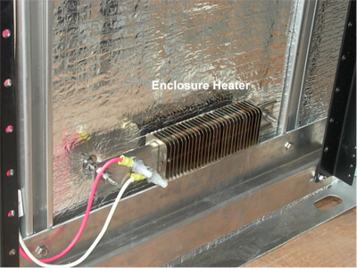
-
Verify operation of cubicle
switchgear/switchboard space
heaters.
-
Perform phasing checks on
double-ended or dual-source
switchgear to insure correct bus
phasing from each source.
-
Perform electrical tests of surge
arresters.
C. Test Values – Visual and
Mechanical
-
Compare bolted connection resistance
values to values of similar
connections. Investigate
values which deviate from those of
similar bolted connections by more
than 50 percent of the
lowest value.
-
Bolt-torque levels shall be in
accordance with manufacturer’s
published data. In the absence
of manufacturer’s published data,
use Table 100.12.
-
Results of the Perform thermographic
survey shall be in accordance with
Section 9. (optional)
D. Test Values –
Electrical
-
Compare bolted connection resistance
values to values of similar
connections. Investigate
values which deviate from those of
similar bolted connections by more
than 50 percent of the
lowest value.
-
Insulation-resistance values of bus
insulation shall be in accordance
with manufacturer’s
published data. In the absence of
manufacturer’s published data, use
Table 100.1. Values of
insulation resistance less than this
table or manufacturer’s
recommendations should be
investigated. Dielectric withstand
voltage tests shall not proceed
until insulation-resistance
levels are raised above minimum
values.
-
If no evidence of distress or
insulation failure is observed by
the end of the total time of
voltage application during the
dielectric withstand test, the test
specimen is considered to
have passed the test.
-
Minimum insulation-resistance values
of control wiring shall not be less
than two megohms.
-
Results of electrical tests on
instrument transformers shall be in
accordance with Section
7.10.
-
Results of ground-resistance tests
shall be in accordance with Section
7.13.
-
Accuracy of metering devices shall
be in accordance with Section 7.11.
-
Control Power Transformers
-
Insulation-resistance values of
control power transformers shall
be in accordance with
manufacturer’s published data.
In the absence of manufacturer’s
published data, use
Table 100.1. Values of
insulation resistance less than
this table or manufacturer’s
recommendations should be
investigated.
-
Turns-ratio test results shall
not deviate by more than
one-half percent from either the
adjacent coils or the calculated
ratio.
-
Secondary wiring shall be in
accordance with design drawings
and specifications.
-
Secondary voltage shall be in
accordance with design
specifications.
-
Control transfer relays shall
perform as designed.
-
Voltage transformers
-
Secondary wiring shall be in
accordance with design drawings
and specifications.
-
Secondary voltage shall be in
accordance with design
specifications
-
Current-injection tests shall prove
current wiring is in accordance with
design specifications.
-
Results of system function tests
shall be in accordance with
ANSI/NETA ECS.
-
Heaters shall be operational.
-
Phasing checks shall prove the
switchgear or switchboard phasing is
correct and in
accordance with the system design.
-
Results of electrical tests on surge
arresters shall be in accordance
with Section 7.19.
NETA MTS-2019
7.1 Switchgear,
Switchboard, and Panelboard
A. Visual and Mechanical
Inspection:
-
Inspect physical, electrical, and
mechanical condition.
-
Inspect anchorage, alignment,
grounding, and required area
clearances.
-
Prior to cleaning the unit, perform
as-found tests, if required
-
Clean the unit.
-
Verify that fuse and/or circuit
breaker sizes and types correspond
to drawings and
coordination study as well as to the
circuit breaker address for
microprocessorcommunication
packages.
-
Verify that current and voltage
transformer ratios correspond to
drawings.
-
Verify that wiring connections are
tight and that wiring is secure to
prevent damage during
routine operation of moving parts.
-
Inspect bolted electrical
connections for high resistance
using one or more of the following
methods:
- Use of a
low-resistance ohmmeter.
- Verify tightness of
accessible bolted electrical
connections by calibrated
torque-wrench
method in accordance with
manufacturer’s published data or
Table 100.12.
- Perform Perform
thermographic survey.
(optional).
-
Confirm correct operation and
sequencing of electrical and
mechanical interlock systems.
-
Attempt closure on locked-open
devices. Attempt to open
locked-closed devices.
-
Make key exchange with all
devices included in the
interlock scheme as applicable.
-
Use appropriate lubrication on
moving current-carrying parts and on
moving and sliding
surfaces.
-
Inspect insulators for evidence of
physical damage or contaminated
surfaces.
-
Verify correct barrier and shutter
installation and operation.
-
Exercise all active components.
-
Inspect mechanical indicating
devices for correct operation.
-
Verify that filters are in place
and/or vents are clear.
-
Perform visual and mechanical
inspection of instrument
transformers
-
Perform visual and mechanical
inspection of surge arresters
-
Inspect control power transformers.
-
Inspect for physical damage,
cracked insulation, broken
leads, tightness of
connections, defective wiring,
and overall general condition.
-
Verify that primary and
secondary fuse ratings or
circuit breakers match drawings.
-
Verify correct functioning of
drawout disconnecting and
grounding contacts and
interlocks.
-
Perform as-left tests.
B. Electrical Tests:
-
Perform resistance measurements
through bolted electrical
connections with a lowresistance
ohmmeter
-
Perform insulation-resistance tests
for one minute on each bus section,
phase-to-phase and
phase-to-ground. Apply voltage in
accordance with manufacturer’s
published data. In the
absence of manufacturer’s published
data, use Table 100.1.
-
Perform a dielectric withstand
voltage test on each bus section,
each phase-to-ground with
phases not under test grounded, in
accordance with manufacturer’s
published data. within
the absence of manufacturer’s
published data, use Table 100.2. The
test voltage shall be
applied for one minute. Refer to
Section 7.1.3 before performing
test. (optional)
-
Perform insulation-resistance tests
on control wiring with respect to
ground. The applied
potential shall be 500 volts dc for
300-volt rated cable and 1000 volts
dc for 600-volt rated
cable. Test duration shall be one
minute. For units with solid-state
components or control
devices that cannot tolerate the
applied voltage, follow
manufacturer’s recommendation.
(optional)
-
Perform electrical tests on
instrument transformers in
accordance with Section 7.10.
-
Perform ground-resistance tests in
accordance with Section 7.13.
-
Test metering devices in accordance
with Section 7.11.
-
Control Power Transformers.
- Perform
insulation-resistance tests.
Perform measurements from
winding-to-winding
and each winding-to-ground. Test
voltages shall be in accordance
with
manufacturer’s published data.
In the absence of manufacturer’s
published data, use
Table 100.1.
-
Verify correct function of
control transfer relays located
in switchgear with multiple
power sources.
-
Verify operation of
switchgear/switchboard heaters and
their controller.
-
Perform electrical tests of surge
arresters.
-
Perform online partial-discharge
survey in accordance with Section
11. (optional)
-
Perform system function tests
C. Test Values – Visual and
Mechanical
-
Compare bolted connection resistance
values to values of similar
connections. Investigate
values which deviate from those of
similar bolted connections by more
than 50 percent of
the lowest value.
-
Bolt-torque levels should be in
accordance with manufacturer’s
published data. In the
absence of manufacturer’s published
data, use Table 100.12.
-
Results of the Perform thermographic
survey shall be in accordance with
Section 9. (optional)
D. Test Values –
Electrical
-
Compare bolted connection resistance
values to values of similar
connections. Investigate
values which deviate from those of
similar bolted connections by more
than 50 percent of
the lowest value.
-
Insulation-resistance values of bus
insulation should be in accordance
with manufacturer’s
published data. In the absence of
manufacturer’s published data, use
Table 100.1. Values of
insulation resistance less than this
table or manufacturer’s
recommendations should be
investigated. Dielectric withstand
voltage tests should not proceed
until
insulation-resistance levels are
raised above minimum values.
-
If no evidence of distress or
insulation failure is observed by
the end of the total time of
voltage application during the test,
the test dielectric withstand
voltage specimen is
considered to have passed the test.
-
Minimum insulation-resistance values
of control wiring should be
comparable to previously
obtained results but not less than
two megohms.
-
Results of electrical tests on
instrument transformers should be in
accordance with Section
7.10.
-
Results of ground resistance tests
should be in accordance with Section
7.13.
-
Accuracy of metering devices should
be in accordance with Section 7.11.
-
Control Power Transformers
-
-
-
Heaters should be operational.
-
Results of electrical tests on surge
arresters shall be in accordance
with Section 7.19.
-
Results of online partial-discharge
survey should be in accordance with
manufacturer’s
published data. In the absence of
manufacturer’s published data, refer
to Table 100.23.
-
Results of system function tests
shall be in accordance with Section
8.
|