Infrared Inspections
Description:
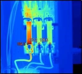
Infrared thermal surveys, also known as thermographic inspections, involve the use of infrared cameras to capture thermal images that illustrate the temperature distribution of electrical equipment while it's in operation. This non-contact, non-destructive testing method detects irregular heat patterns that may indicate potential problems such as loose connections, overloaded circuits, or other anomalies in electrical components.
Common Issues
Overheating Issues:
Infrared inspections can detect overheating electrical components such as
wires, switches, circuit breakers, and connections. Overheating is a common precursor to electrical
failures and can lead to fires or equipment damage. Detecting these issues early can prevent catastrophic
failures.
Failure Prevention:
By identifying and addressing potential issues before they escalate, you can prevent unplanned downtime in your
facility. Downtime can be costly in terms of lost production, revenue, and repair expenses.
Increase Equipment Lifespan:
Regular inspections can extend the lifespan of electrical equipment. Overheati issues early can help equipment last longer.
Specific Applications:
Preventive Maintenance:
Regularly scheduled infrared surveys can help in detecting early signs of failure in electrical systems.
Quality Assurance:
Verifies the integrity of electrical installations and repairs.
Condition Monitoring:
Continuous monitoring of critical equipment can prevent catastrophic failures and unscheduled downtime.
Energy Audits:
Identifying heat losses in electrical systems can lead to energy savings by addressing inefficiencies.
Pros:
Non-Invasive:
Does not require shutdown or contact with the equipment, allowing for ongoing operations without interruption.
Early Detection:
Identifies potential failures before they lead to major damage, reducing repair costs and downtime.
Safety Enhancement:
Reduces the risk of fires and increases safety by early detection of overheating parts.
Cost Savings:
Helps in saving costs by preventing large-scale repairs and energy wastage.
Cons:
Initial Cost:
The equipment and expertise required for infrared thermal imaging can be expensive
Training Requirements:
Requires trained personnel to interpret thermal images accurately.
Limited Reach:
May not detect issues deep within enclosed or compact systems unless there's a clear line of sight.
Periodic Inspections:
Being a snapshot in time, it requires periodic surveys to ensure continuous protection.
| NETA Test Procedure | |
|---|---|
Thermographic Survey
NETA ATS-2017Thermographic Survey1. Visual and Mechanical Inspection
2. ReportProvide a report which includes the following:
3. Test Parameters
4. Test Results
NETA ATS-20179. THERMOGRAPHIC SURVEY1. Visual and Mechanical Inspection
2. Thermographic Survey ReportProvide a report which includes the following:
3. Test Parameters
4. Test Results
NETA
ATS / MTS
TABLE
100.18
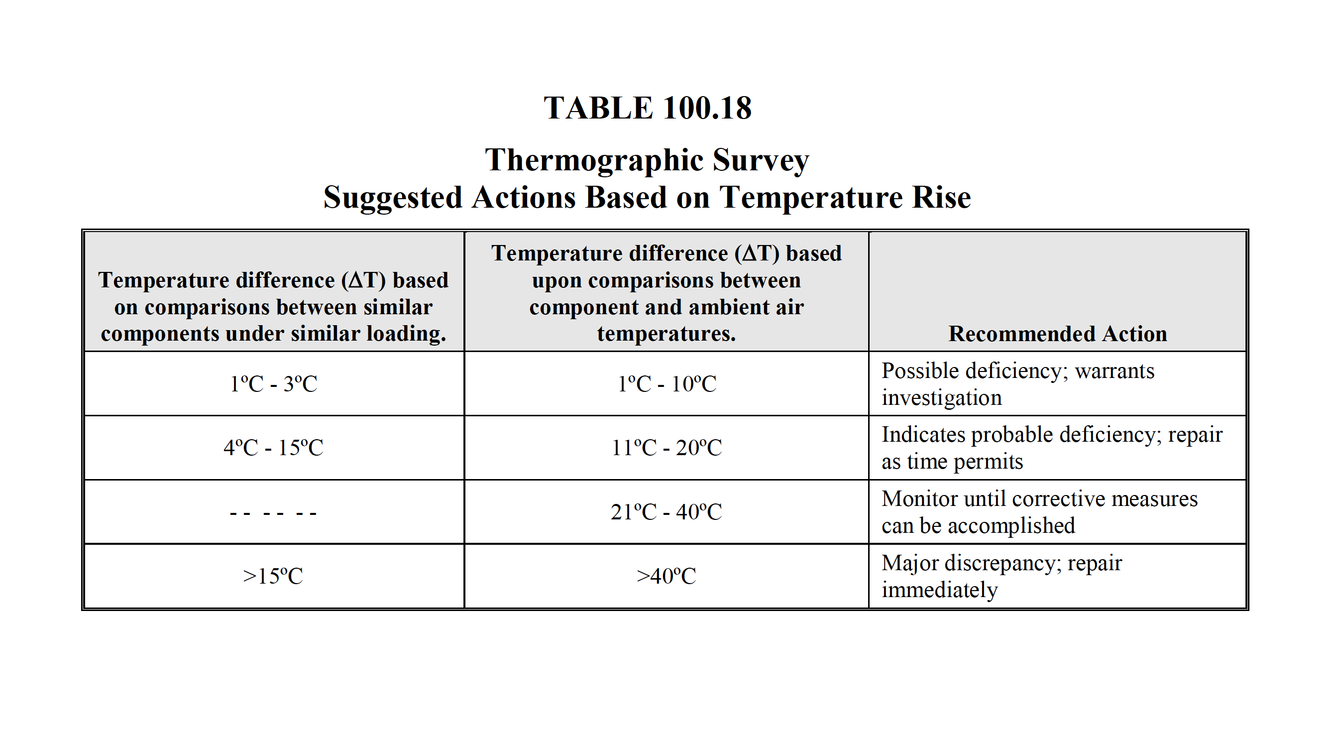
Temperature specifications vary depending on the exact type of equipment. Even in the same class of equipment (i.e., cables) there are various temperature ratings. Heating is generally related to the square of the current; therefore, the load current will have a major impact on ΔT. In the absence of consensus standards for ΔT, the values in this table will provide reasonable guidelines. An alternative method of evaluation is the standards-based temperature rating system as discussed in Chapter 8.9.2.2, Conducting an IR Thermographic Inspection, Electrical Power Systems Maintenance and Testing, by Paul Gill, PE, 2008 edition. It is a necessary and valid requirement that the person performing the electrical inspection be thoroughly trained and experienced concerning the apparatus and systems being evaluated as well as knowledgeable of thermographic methodology. |
|